
Development and Application of Weld Strength Improvement Technology for Rolling Bearing Resin Cages
August 2026
Polymer Research Group, Technology Research & Development Office 2
Core Technology R&D Center, Technology Development Division Headquarters
1. Introduction
Conventionally, cages for rolling bearings were made of metal, but in recent years, the adoption of resin cages has been promoted due to their lightweight properties and high design flexibility. Fiber-reinforced resins further reinforced with glass fibers or carbon fibers are often used for resin cages. However, at the resin confluence (weld) formed when manufacturing annular resin cages by injection molding, the fibers do not align in the target circumferential direction, and the reinforcing effect is not exhibited, which presents a challenge in promoting the adoption of resin cages. We developed a method to improve the weld strength of resin cages by providing a structure called a reservoir in the injection mold, thereby orienting the fibers at the weld in the circumferential direction. We verified and reproduced this effect through both experiments and analysis, defining an index that expresses the influence of the reservoir's capacity and position on the weld strength through analysis. Furthermore, by establishing a threshold for this index, we devised an appropriate reservoir design method to improve weld strength. Resin cages designed using this method are already being applied to some rolling bearings. In this article, we review on the development of this technology and introduce the status of related patent applications and rights acquisition, as well as the status of its application to NSK rolling bearings.
2. Overview of our Developed Technology
2.1 Verification of Effects by Applying Reservoirs
Using the simple ring-shaped test specimen (hereafter “ring specimen”) shown in Fig.1, we verified the effects of the capacity and position of the reservoir on weld strength1). In the observation of fiber orientation using X-ray CT, it was confirmed that by providing the reservoir at a location shifted from the weld, the fibers at the weld were oriented nearly in the desired circumferential direction (Fig.2). Through the measurement of weld strength, it was confirmed that the weld strength increased when the capacity of the reservoir was large and when the reservoir was located closer to the weld (Fig.3). On the other hand, when the reservoir was provided directly at the weld, almost no strength improvement was obtained regardless of the reservoir capacity.
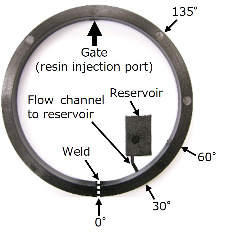
Fig.1 Ring-shaped test specimen
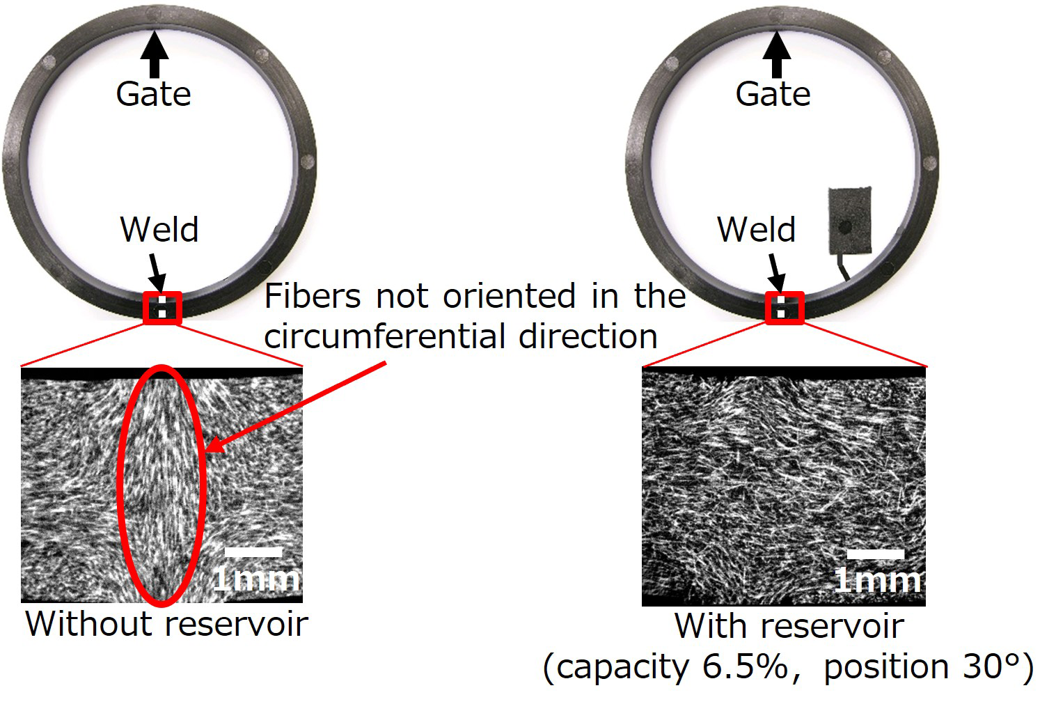
Fig.2 Fiber orientation around the weld of the ring specimen
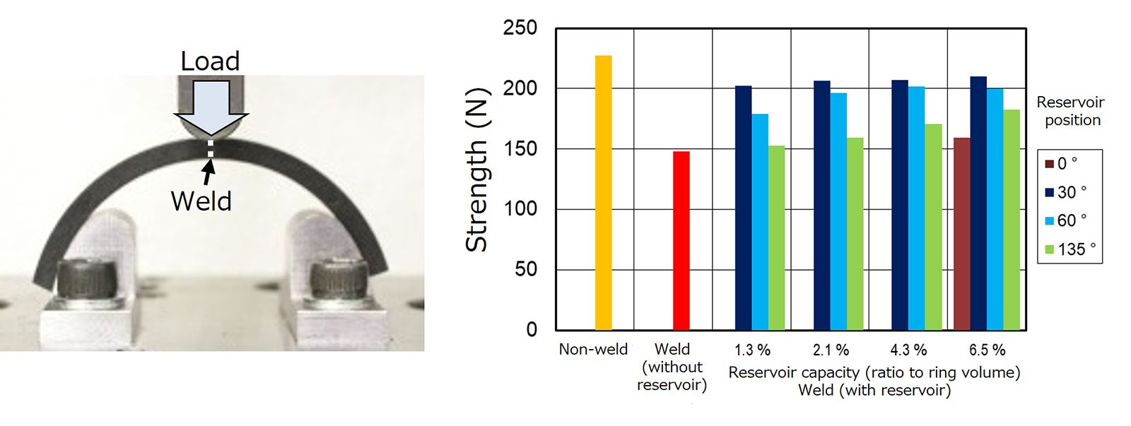
Fig.3 Weld strength measurement results of ring specimen
2.2 Proposal of Weld Strength Evaluation Index in Analysis
Using the model of the ring specimen mentioned above, we worked on reproducing the resin flow behavior through resin flow analysis1). Similar to the experimental results, it was confirmed in the analysis that by providing the reservoir at a location shifted from the weld, the fibers at the weld were oriented nearly in the desired circumferential direction (Fig.4). As an evaluation index for weld strength in the analysis, we introduced resin displacement, defined as the product of resin flow time and resin flow velocity. The resin displacement is a quantity corresponding to the travel distance obtained by dividing the volume of resin that passed through a specific cross section of the flow path by its cross-sectional area (Fig.5). When organizing the analysis results using this index, results were obtained that matched well with the experimental results: the larger the reservoir capacity and the closer its location to the weld, the larger the resin displacement (Fig.6). Further examining the relationship between the weld resin displacement obtained by analysis and the weld strength obtained by experiment revealed that the weld strength saturates when the resin displacement reaches 2.7 mm or more (Fig.7). Therefore, we determined resin displacement of 2.7 mm as the threshold value for judging the presence or absence of the weld strength improvement effect by the reservoir using resin flow analysis.
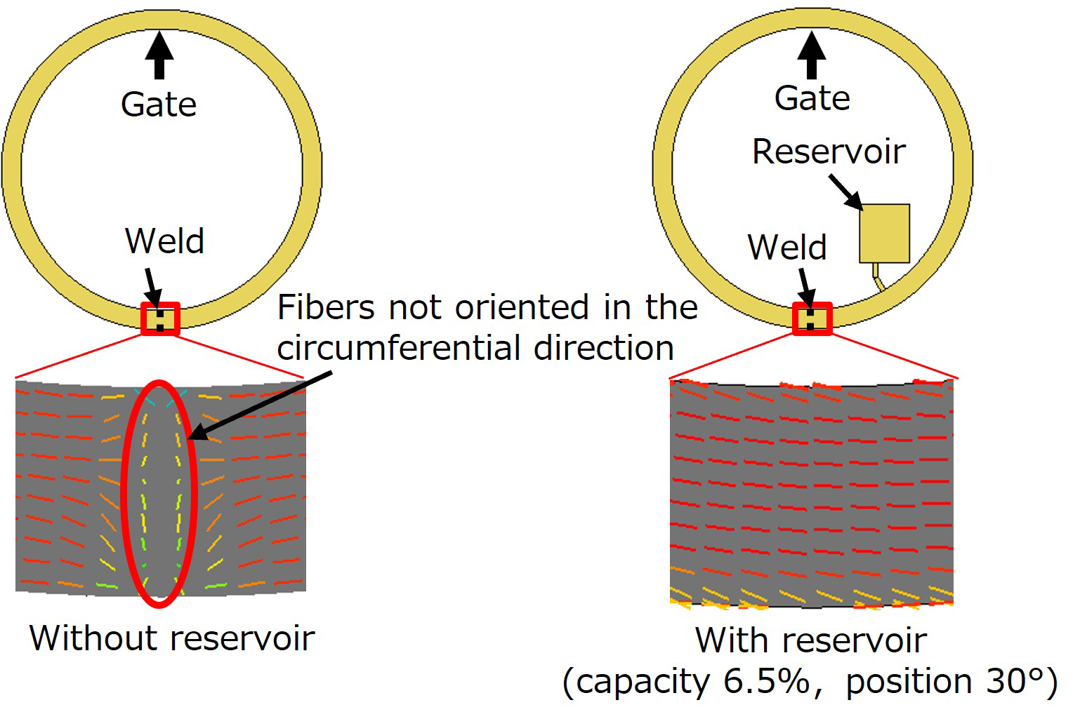
Fig.4 Fiber orientation analysis results around the weld of ring specimen
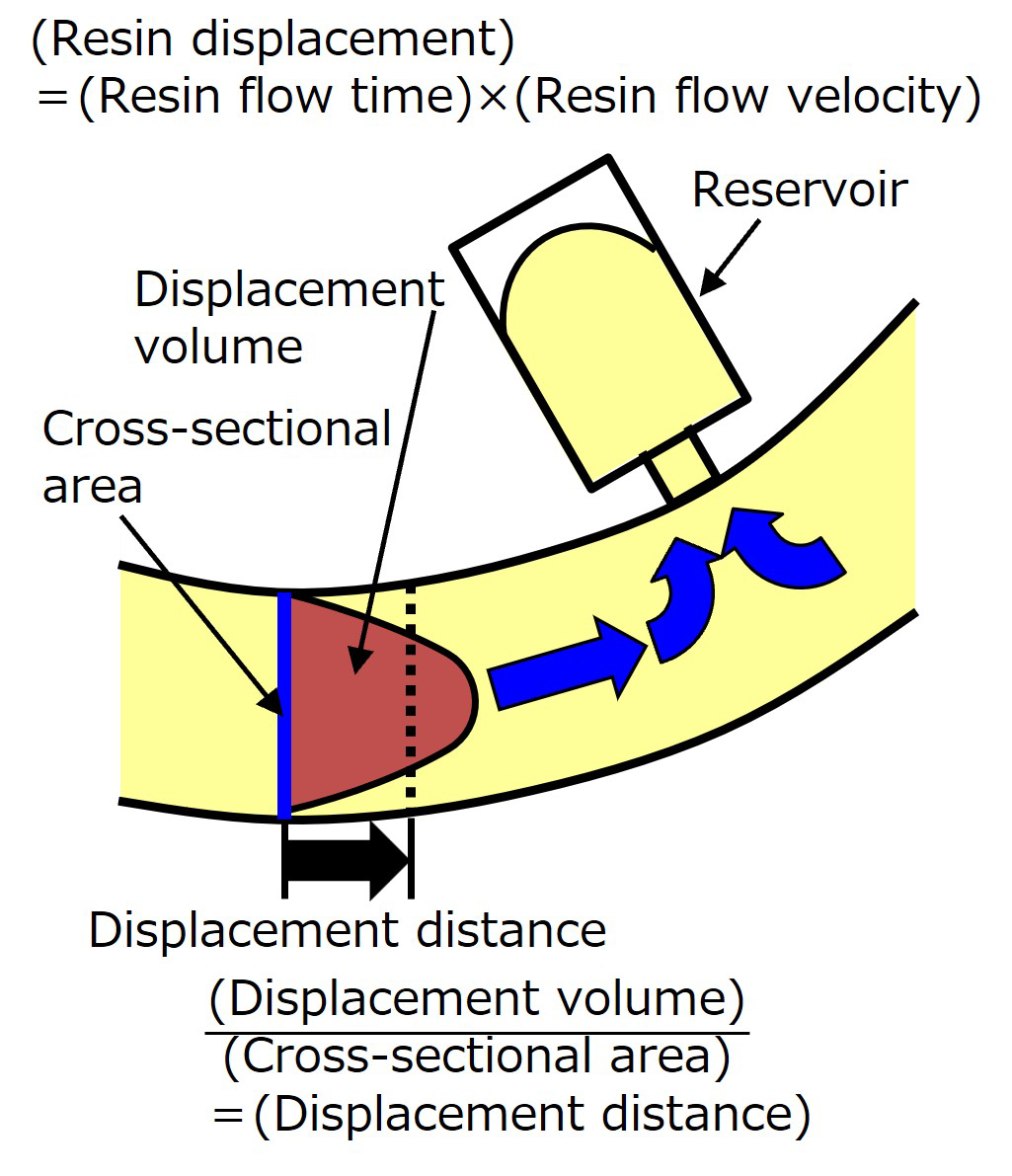
Fig.5 Conceptual diagram of resin displacement
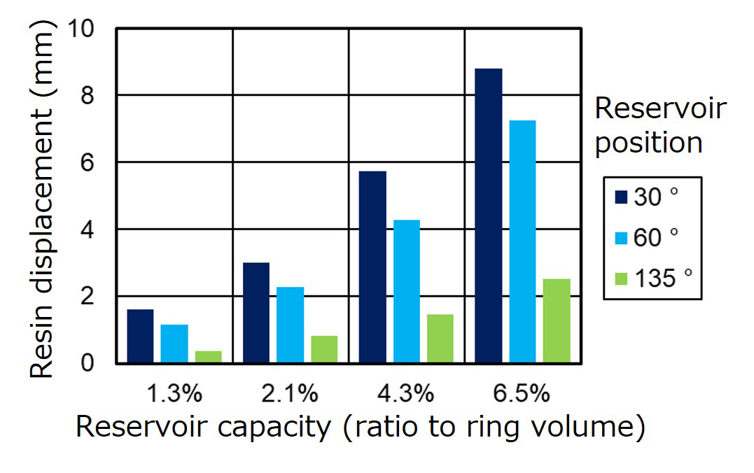
Fig.6 Weld resin displacement calculation results in ring specimen
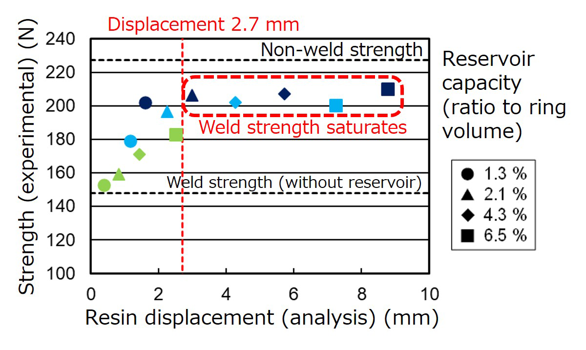
Fig.7 Comparison of weld strength (measured) and weld resin displacement (analysis)
2.3 Verification of Cage Geometry
The findings obtained from the verification of the ring specimen were applied to a crown-type resin cage and a machined-type resin cage*, and their effects were confirmed 1). Resin flow analysis was performed using analysis models providing reservoirs on the cages, and the weld resin displacements were calculated. Prototype crown-type and machined-type cages were fabricated using molds with reservoirs of capacities and positions that yielded resin displacements exceeding 2.7 mm, and their weld strengths were measured. In the crown-type cage, the weld strength without a reservoir decreased to 62% of the non-weld area, but by providing an appropriate reservoir, results showed that the weld strength improved to a level equivalent to the non-weld area (Fig.8). In the machined-type cage, the weld strength without a reservoir decreased to 47% of the non-weld area, but by providing an appropriate reservoir, results showed that the weld strength improved up to 85% of the non-weld area (Fig.9). Hence, it was demonstrated that for actual cage geometry, weld strength can be improved by applying resin flow analysis to install reservoirs with optimized capacity and position.
* In this article, a cage fabricated by injection molding to imitate a general machined cage is referred to as a machined-type cage for convenience.
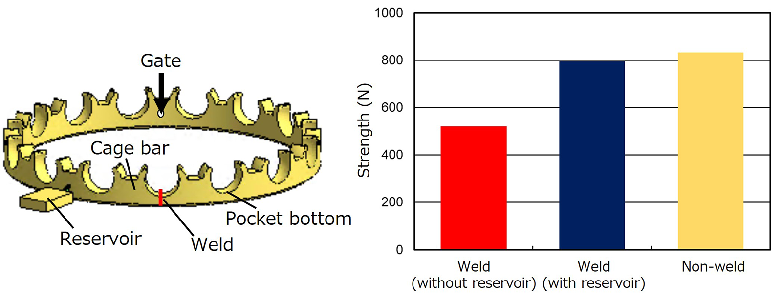
Fig.8 Crown-type cage and its strength measurement results
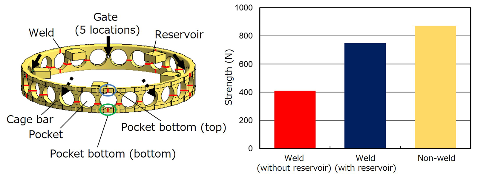
Fig.9 Machined-type cage and its strength measurement results
3. Status of Related Patent Applications and Patent Rights
Patent applications have been filed for cages with improved weld strength by applying reservoirs and their manufacturing methods, and 28 patents have already been registered in Japan. Rights acquisition is also progressing overseas, with two patents registered in the United States, one patent in China, and one patent in the United Kingdom.
4. Status of Application of This Technology to NSK Rolling Bearings
The weld strength improvement technology described above has been applied to certain part numbers of the high-speed angular contact ball bearing SURSAVE™ cage. SURSAVE cages are applied to bearings for machine tool main spindles, achieving lower bearing vibration and lower torque compared to when conventional cages are applied2). In particular, when a weld is formed at the thin-walled pocket bottom, there is a concern about a reduction in cage strength. Therefore, for part numbers where welds are formed at the pocket bottom, we decided to manufacture cages with improved weld strength using molds equipped with reservoirs whose capacity and position were optimized by applying the aforementioned index. Mass production of part numbers applying this technology started in 2019, and as of June 2026, it has been applied to three part numbers. We plan to further expand the applicable part numbers in the future.
Here, we introduce an example of strength evaluation at the prototype stage of a resin cage for a part number applying this technology. In the cage of this part number, a weld is formed at the thin pocket bottom, raising concerns about strength reduction. Therefore, to improve the weld strength at the pocket bottom, prototype cages were fabricated applying reservoirs optimized for capacity and position. From the prototype resin cages, specimens were cut from pockets where weld strength was expected to be improved by this technology and from pockets in which no weld line was formed at the pocket bottom, and the strength at the pocket bottom was measured. As a result, it was confirmed that the pocket expected to have improved weld strength [weld (with reservoir)] possessed strength equal to or higher than the pocket where no weld was formed at the pocket bottom (non-weld) (Fig.10). From these results, it was confirmed that by applying this technology to improve weld strength, concerns regarding strength reduction in the SURSAVE cage can be resolved.
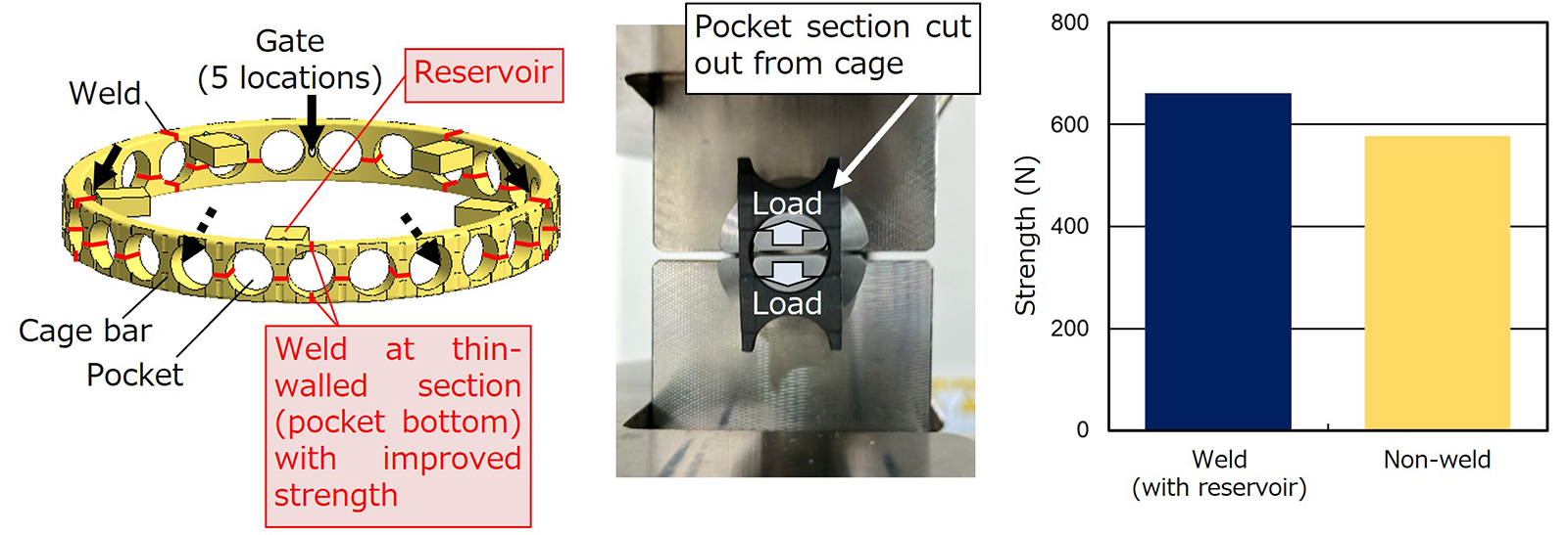
Fig.10 Strength measurement results at the prototype stage of the SURSAVE cage applying this technology
5. Conclusion
In this article, we introduced an overview of the technology that improves weld strength by providing a reservoir in the injection mold to orient the fibers in the circumferential direction at the weld formed during the manufacturing of resin cages for rolling bearings, the status of related patent applications and rights acquisition, and the status of its application to NSK rolling bearings. Going forward, by applying this technology to expand the scope of application for resin cages, we will promote weight reduction in rolling bearings and contribute to carbon neutrality.
Although the overview of this technology was introduced in Section 2, those who wish to know more details are encouraged to refer to Reference 1).
References
1) NSK Ltd., "Enhancement of Weldline Strength by Applying a Reservoir to the Plastic Cage of a Rolling Bearing," NSK Technical Journal MOTION & CONTROL, No. 33, (2022) 91–101
2) NSK Ltd., " Ultra High Speed Angular Contact Ball Bearings with Newly Developed SURSAVE Cage," NSK Catalog, CAT. No. ESP-161101a, (2016) 1–2