
Lightweight and Low-Cost Magnetostrictive Torque Sensor for Mobility and Robotics Applications
October 2026
Product Development Office
Automotive New Product Development Department
Automotive Technology Development Center
1. Introduction
In recent years, control technologies using torque information have become sophisticated in the fields of mobility and robotics. Torque information has become a critical control parameter in various applications: for e-Bikes, in pedal assist control; for robots, in coordinated motion and contact force control; and for automobiles, in the optimal control of drive and braking forces.
To date, our company has developed magnetostrictive torque sensors suitable for high-speed rotating shafts, primarily for automotive powertrains. Because torque can be measured without contact with the shaft, magnetostrictive torque sensors offer high durability, high reliability, and compact dimensions.
On the other hand, in recent years, there has been growing demand for their application to low-speed rotating shafts, as exemplified by e-Bikes and rotary actuators for robots. Also, from the perspective of improving safety and reliability, there is a growing demand for redundant configurations equipped with fault detection functions. Therefore, based on our conventional sensor heads for high-speed rotating shafts, we developed a 4th-generation sensor head optimized for low-speed rotating shafts—featuring a lighter weight and lower cost—and also developed a magnetostrictive torque sensor with a dual-signal configuration to enhance reliability.
2. Magnetostrictive Torque Sensor Overview
2.1 Magnetostrictive Torque Sensor Configuration
Fig.1 and Fig.2 show the system configuration and external appearance of the sensor head for this magnetostrictive torque sensor. This magnetostrictive torque sensor consists of three main components: the sensor head, the shaft, and the signal processor.
The sensor head is a ring-shaped component, as shown in Fig.2. It contains a flexible printed circuit (FPC) with coil patterns formed on it, and the shaft to be measured passes through its center. Because the FPC is positioned without contact with the shaft, sensing elements do not need to be attached to the rotating shaft, resulting in high durability and reliability.
The signal processor has three functions: exciting the sensor head, processing the electrical signals received from the sensor head, and outputting torque values to higher-level control devices such as in-vehicle controllers.
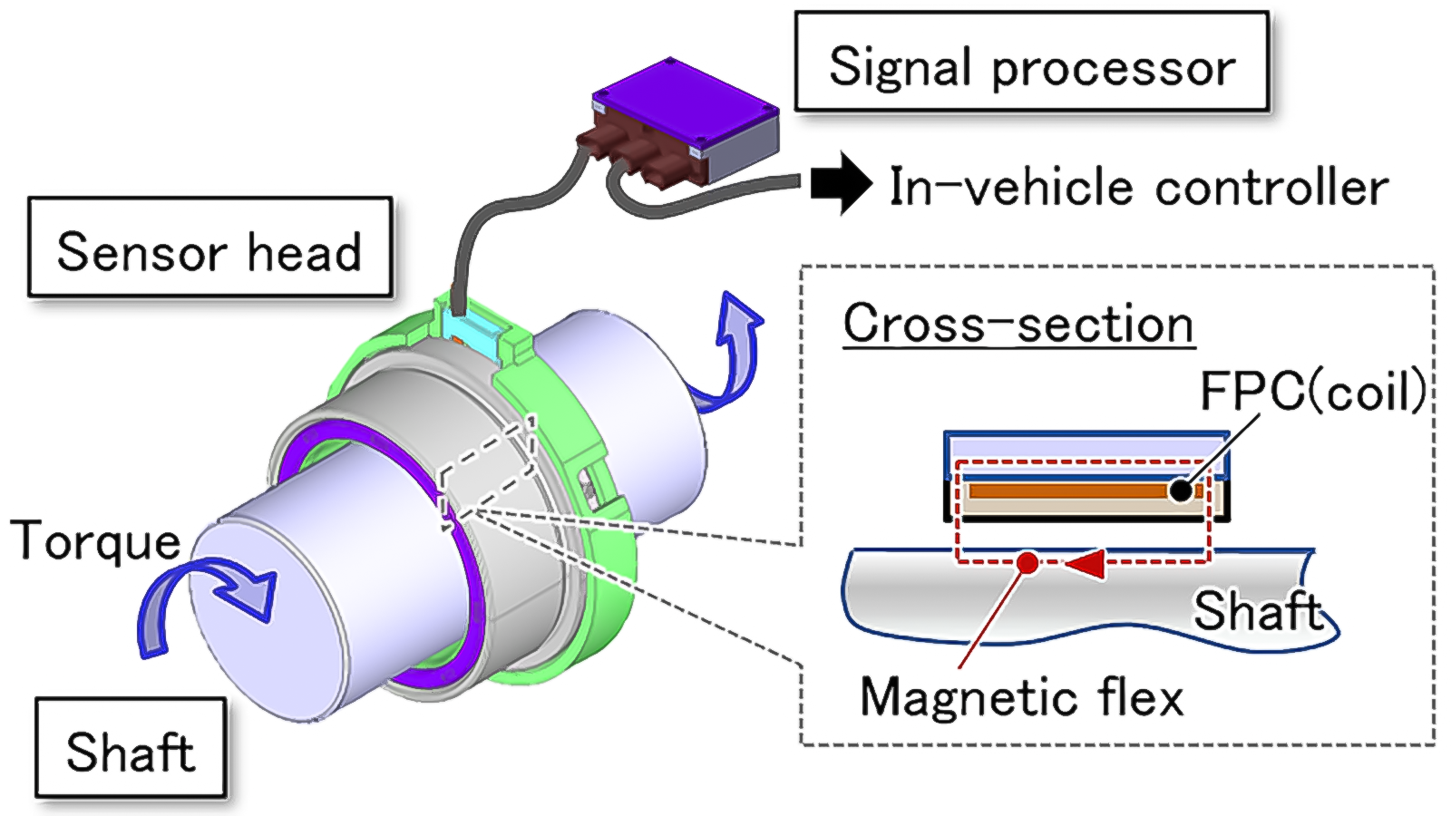
Fig.1 System Configuration

Fig.2 3rd-Generation Sensor Head
2.2 Torque Detection Flow
When detecting torque with this magnetostrictive torque sensor, the signal processor first applies a current to the sensor head. This current excites the coil inside the sensor head, generating a magnetic field between the sensor head and the shaft, causing a magnetic flux to pass through the surface of the shaft. In this state, when the shaft is twisted (torque is applied) and stress is generated in the shaft, a phenomenon known as the inverse magnetostriction effect occurs1). The inverse magnetostriction effect is a phenomenon in which the magnetic properties of a magnetic material, such as iron, change when an external force distorts its crystal structure. As a result, the permeability of the shaft under torque changes. When the permeability of the shaft changes, the amount of magnetic flux generated by the coil inside the sensor head changes, causing the coil inductance to vary. Since this change in inductance can be converted into an electrical signal, signal processing—such as amplification and filtering—enables the output to be an electrical signal that varies with torque.
2.3 Torque Detection Accuracy
There are three main sources of error affecting the torque detection accuracy of this magnetostrictive torque sensor.
The first error, as shown in Fig.3[A], is caused by the twisting of the shaft due to the applied torque. This error includes hysteresis error and nonlinearity error. This is considered to be caused by the magnetostrictive characteristics of the shaft material and is referred to as “torque-induced nonlinearity including hysteresis”.
The second error, as shown in Fig.3[B], is caused by changes in ambient temperature. This is referred to as “temperature-induced zero-point drift”.
The third error, as shown in Fig.3[C], is caused by the shaft’s angle of rotation. The sensor output signal fluctuates periodically as the shaft rotates. This phenomenon is considered to be caused by circumferential non-uniformity in the shaft’s magnetic permeability and is referred to as “shaft-rotation-angle-induced zero-point variation”.
In the development of this magnetostrictive torque sensor, the sum of the above three types of errors was defined as the overall accuracy and used as an indicator for performance evaluation.
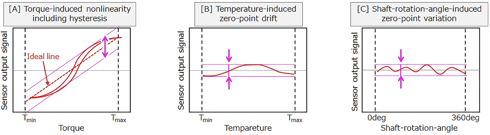
Fig.3 Torque Detection Accuracy
3. Sensor Head for Low-Speed Rotating Shafts Development
3.1 Development Background
Conventional 3rd-generation sensor head was originally developed for high-speed rotating shafts used in automotive powertrains.
On the other hand, e-Bikes and robotics actuators operate at relatively low rotational speeds and do not necessarily require the high-temperature countermeasures or non-contact shaft structure adopted in conventional designs. Therefore, there was potential for further weight and cost reduction for low-speed rotating shafts.
3.2 Sensor Head Structure Improvements
Fig.4 shows the structure of the 4th-generation sensor head. This sensor head employs a structure in which the sensor head is supported and guided by the shaft being detected. Additionally, the back yoke used in the conventional structure was eliminated, and the design was changed to a structure primarily made of resin. This resulted in a reduction in the number of parts, lower weight, and lower cost. The developed sensor head weighs 14 g, achieving a weight reduction of approximately 80% compared with the conventional structure.
3.3 Sensor Accuracy Evaluation Results
We evaluated sensor accuracy by “torque-induced nonlinearity including hysteresis”, “temperature-induced zero-point drift”, and “shaft-rotation-angle-induced zero-point variation”.
For the evaluation, a shaft was used that incorporated shot peening technology developed for magnetostrictive torque sensors for automotive powertrains. This shaft achieves improved sensitivity without using the high-sensitivity coating typically employed in e-Bikes. The shaft was made of alloy steel and designed as a hollow shaft with an outer diameter of φ30.8 mm and an inner diameter of φ27.8 mm. Furthermore, after carburizing, quenching, and tempering, the torque detection section was polished and shot-peened.
The sensor was evaluated under conditions with a torque range of 0–100 N·m and a temperature range of –20 to +85 °C. Fig.5 shows the evaluation results. The results confirmed that the overall accuracy was within 10%, verifying the basic performance for low-speed rotating shaft applications.
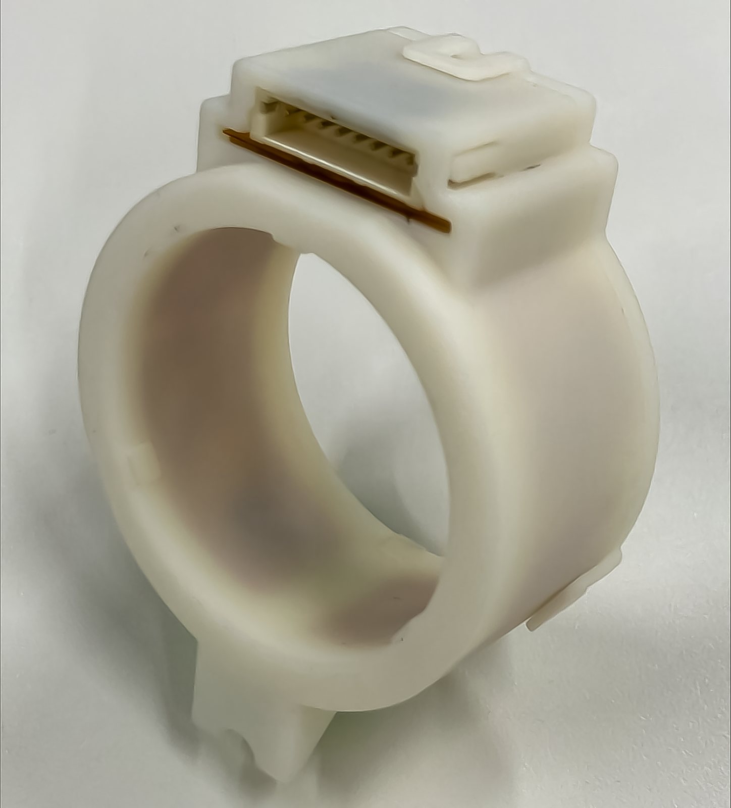
Fig.4 4th-Generation Sensor Head
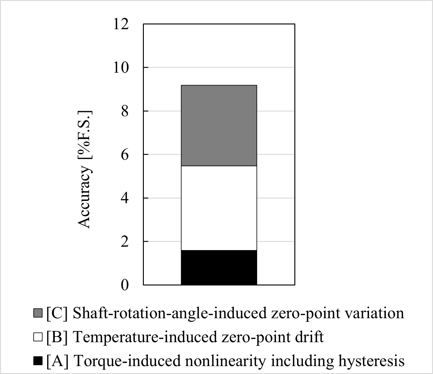
Fig.5 Sensor Accuracy
4. Dual-signal Torque Sensor Development
4.1 Development Background
In recent years, compliance with safety functions has become increasingly important in the mobility and robotics industries, particularly for applications such as e-Bikes and collaborative robots. Consequently, a redundant configuration is required for torque sensors to enable fault detection and provide backup.
4.2 Dual-signal Structure
Fig.6 shows the configuration of the dual-signal system. In this development, the coil pattern on the FPC in the 4th-generation sensor head was optimized to arrange two independent coils within a single sensor head. These coils constitute two independent sensing channels. This enabled the implementation of a dual-signal structure while maintaining the same size and weight. Furthermore, by applying different excitation frequencies to each system, magnetic interference was suppressed, enabling independent torque detection.
4.3 Sensor Accuracy Evaluation Results
Fig.7 shows the results of evaluating the accuracy of the dual-signal torque sensor under the same conditions as those described in Section 3.3. It was confirmed that torque detection can be performed using two independent detection systems even in the dual-signal configuration. However, there is potential for improvement in overall accuracy; in particular, it was confirmed that “shaft-rotation-angle-induced zero-point variation” has a significant impact. Moving forward, we will aim to improve overall accuracy by reducing each error factor through modifications to the sensor head and shaft.
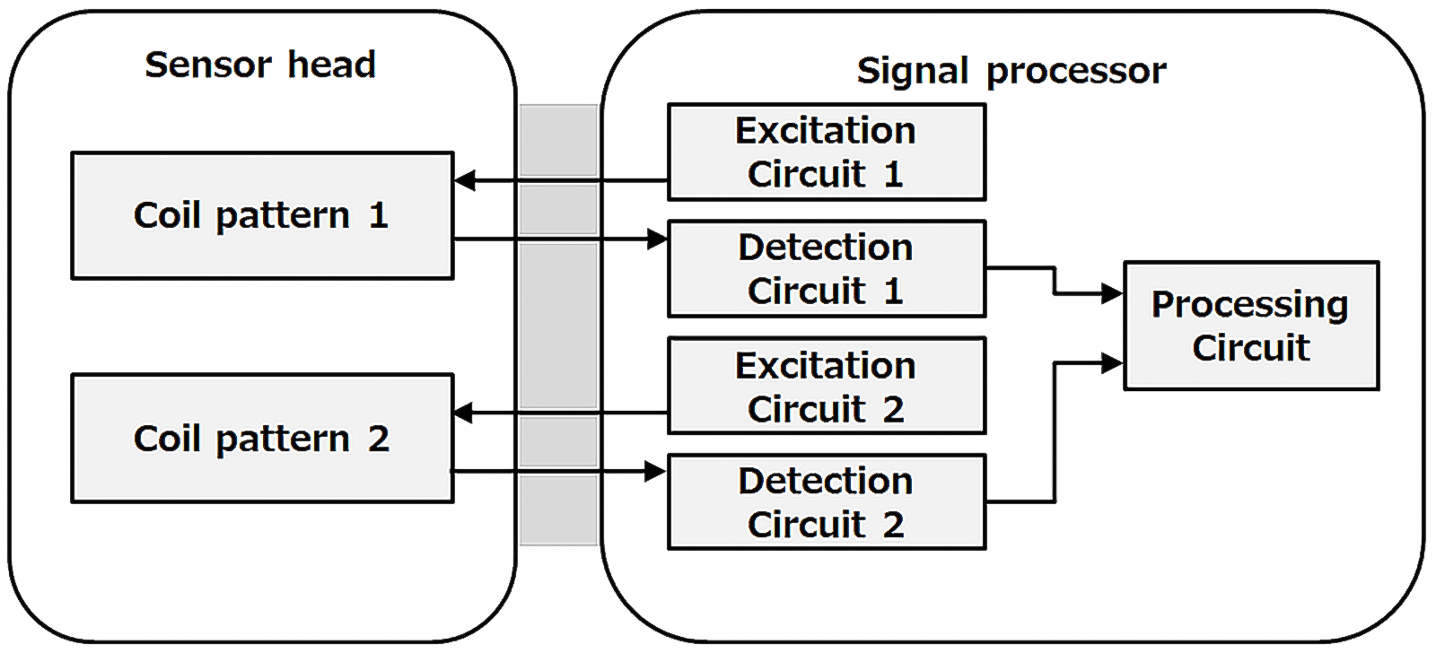
Fig.6 Dual-signal Configuration
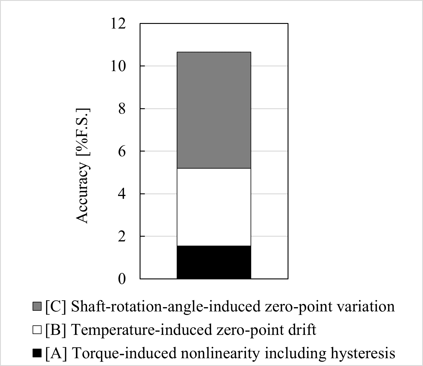
Fig.7 Sensor Accuracy of the Dual-signal Configuration
5. Conclusion
In this development, we developed a low-weight, low-cost 4th-generation sensor head for low-speed rotating shafts and established a dual-signal technology that contributes to the safety functions of the systems in which it is applied. Furthermore, we prototyped a dual-signal magnetostrictive torque sensor incorporating two independent detection systems within a single sensor head and verified its basic performance. These technologies are expected to be applicable to e-Bikes, collaborative robots, and humanoid robots.
Moving forward, we will continue to pursue higher accuracy, further miniaturization, and improved reliability to advance practical applications in the mobility and robotics industries.
This magnetostrictive torque sensor is being jointly developed by NSK Ltd. and Proterial Cable Solutions, Ltd.
References
1) T. Nakamura, Y. Sugiyama, H. Shimizu, “Magnetostrictive Torque Sensor for In-Vehicle Transmissions”, Hitachi Metals Technical Review, Vol. 35 (2019), 18–23.
2) K. Fukuda, J. Ono, T. Miyazaki, S. Okada, “Proposal to apply Magnetostrictive Torque Sensor in EV” JSAE Annual Congress (Spring), 20195291 (2019)
3) K. Nakai, K. Fukuda, S. Oyama, “Development of Magnetostrictive Torque Sensor System” JSAE Annual Congress (Spring), 20245154 (2024)