
8—Preload
Unlike plain bearings, rolling bearings can be made to have a negative internal clearance or “preload”.
Bearing Preload
Rolling bearings are typically operated with a clearance.
However, they can assembled in a way that applies a negative clearance, causing internal stress that provides favorable characteristics in certain situations, such as when aiming to control shaft runout or increase rigidity.
While under this stress, the measured clearance is zero, and the inner/outer rings and rolling elements are elastically deformed.

This state is called preload.
Preload is often applied to angular contact ball bearings and tapered roller bearings, which are typically mounted in opposed pairs with adjustable clearance.
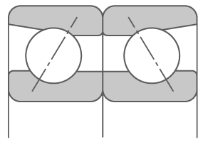
Angular contact ball bearing
Back-to-back arrangement (DB)
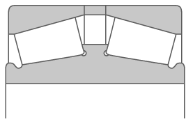
Tapered roller bearing
Front-to-front arrangement (DB)
Why Use Preload?
Preload can be used to:
- Accurately position the shaft in the radial and axial directions and reduce runout.
・Machine tool spindles, measuring instruments, etc. - Increase bearing rigidity:
・Machine tool spindles, automobile differential pinions, etc. - Prevent noise from axial vibrations and resonance:
・Small electric motors, etc. - Suppress unwanted gyratory sliding and spin slide in the rolling elements:
・Applications using high-speed angular contact ball bearings, thrust ball bearings, etc. - Keep the rolling elements in the correct position relative to the rings:
・Thrust ball bearings, spherical roller thrust bearings, etc. used with horizontal shafts
Rigidity
Rigidity is an object’s resistance to deformation from external forces. In other words, it is an object’s capacity to maintain its original shape.


When under load, a bearing’s rolling elements and rings change shape. This change, called elastic deformation, reverts when the load is removed.
A bearing with “high rigidity” undergoes little elastic deformation.
High bearing rigidity → Low misalignment of the rotating shaft under load
In general, roller bearings have higher rigidity than ball bearings, and preloaded bearings are more rigid than bearings without preload.
Preload Methods

Preload and Rigidity
The axial displacement of a single bearing without preload is about one-third to one-half that of a preloaded bearing at the same axial load.
In other words, a preloaded bearing has 2x to 3x higher rigidity.
In general, position preload is good for increasing rigidity.
Meanwhile, constant-pressure preload is suited for high-speed rotation, preventing axial vibration, or use in thrust bearings on horizontal shafts.
Definitions:
Fa: Axial load
δa: Axial displacement under position preload, constant-pressure preload, or no preload with Fa applied

Preload Loss
When applying preload to angular contact ball bearings and tapered roller bearings, back-to-back (DB) arrangements are often used because of the long distances between effective load centers and high overall rigidity.
The figure on the right below shows the displacement (internal clearance/preload) between the inner rings δa0 in a bearing arrangement before mounting. When Bearing A and B are brought together in the axial direction and the inner rings come into contact, the clearance/displacement δa0 between them is eliminated and a preload Fa0 is generated.
When external axial load Fis applied to Bearing A, preload Fa0 and external load Fa act on Bearing A, reducing its axial displacement while reducing the displacement in Bearing B.
In other words, as Faincreases, δa increases while the axial displacement δaB of Bearing B becomes zero, negating the preload. This condition is called preload loss.

Preload in a back-to-back arrangement

Axial displacement with position preload
Definitions:
δa0: Preload gap between inner rings
δa0A: Preload gap of Bearing A
Fa: External axial load
FaA: Axial load imposed on Bearing A under Fa
FaB: Axial load imposed on Bearing B under Fa
δa: Displacement of system (combination bearing) under Fa
δaA: Displacement of Bearing A under Fa
δaB: Displacement of Bearing B under Fa
Fa0: Preload
δa0B: Preload gap of Bearing B
Applying Position Preload
Position preload can be applied by:
- Using a paired mounting with previously adjusted axial clearance and stand-out dimensions.
- Using spacers or shims with previously adjusted dimensions.
- Tightening the bearing axially using bolts, nuts, shims, etc.
⇒This is usually performed to check the starting torque (starting friction moment) and adjust the preload.
Methods 1 and 2 are most common.

Adjusting the width of the inner/outer rings applies the proper preload.
(This shows the appearance before mounting.
Once mounted, the inner rings will contact each other.)

Adjusting the width of the spacer applies the proper preload.
(This shows the appearance before mounting.
Once mounted, the inner ring and spacer will contact each other.)

Appropriate preload is applied by adjusting the shim.
Position Preload: Universal Arrangements

Position Preload: Stand-Out Measurements (DB Arrangements)
Stand-out refers to the difference between the inner and outer ring end faces as indicated by f and b below. It is the difference between the assembled width and inner/outer ring width.
To find the axial clearance using stand-out measurements for a back-to-back arrangement of tapered roller bearings:
- Place the bearing on a stand with its inner ring back face facing down and rotate the outer ring at least 10 turns to stabilize the rollers. Then, measure the inner ring width and assembled bearing width.
- Measure the inner ring width and assembled bearing width for the other bearing to be used in the arrangement as well.
- Then, measure the width dimensions of K (outer ring spacer) and L (inner ring spacer).
")
The axial clearance Δa can be calculated by inputting these measurements into the equation below:
")
Position Preload: Stand-Out Measurements (DF Arrangements)
To find the axial clearance using stand-out measurements for a face-to-face arrangement of tapered roller bearings:
- Place the bearing on a stand with its inner ring front face facing down and rotate the outer ring at least 10 turns to stabilize the rollers. Then, measure the outer ring width and assembled bearing width.
- Measure the outer ring width and assembled bearing width for the other bearing to be used in the arrangement as well.
- Then, measure the width dimensions of K (outer ring spacer) and L (inner ring spacer).
")
The axial clearance Δa can be calculated by inputting these measurements into the equation below:
Many DF arrangements do not have an inner ring spacer, so the back faces of the inner rings often contact each other. In these cases, L= 0.
")
Constant-Pressure Preload
A constant-pressure preload is achieved by coil springs, disc springs, corrugated washers, or similar to consistently ensure a proper level of preload, even if the bearings move during mounting or operation. This method suits applications where preload must remain nearly constant.


With a spring

With multiple springs

With a spring
Required Preload for Thrust Bearings
Bearings are often subjected to high-speed rotation, rapid acceleration and deceleration, and severe fluctuating loads. These conditions can cause smearing due to slippage between the rolling elements and raceway surfaces or scoring in roller bearings.
A certain minimum load is required to control unwanted slipping and scoring.
For thrust ball bearings, the required minimum axial load is the larger of the two values obtained from the following equation:


where:
Fa min: Minimum axial load (N)
C0a: Basic static axial load rating (N)
n: Bearing rotational speed (min-1)
Nmax: Bearing limiting speed (min-1)
Preload for Spherical Roller Thrust Bearings
The required minimum axial load is determined by the following equation:


Importance of Proper Preload
If preload is too high
Excessive preload causes load to be generated between the rolling elements (rolling contact surfaces) and rings (raceway surfaces) separately from the external load. This additional load may cause abnormal heat generation, increased frictional moments, and reduced fatigue life.
If preload is too low
External load may cause an internal clearance, resulting in insufficient bearing rigidity or preload loss. These effects may impact intended performance, making it impossible to achieve proper control of shaft runout or other characteristics.