3—Loads and Loaded Zones
The load handled by a rolling bearing is applied either to part of the raceway surface or across the entire circumference of the bearing. The area where load is applied is called the “loaded zone”.
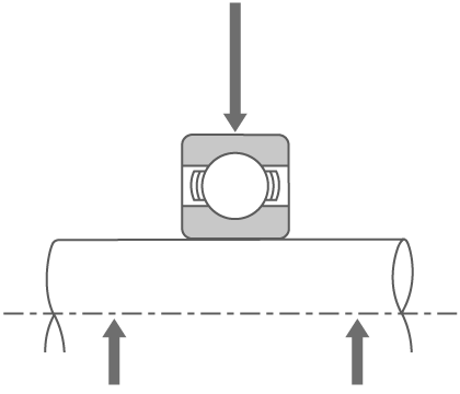
Radial load
Load perpendicular to the shaft
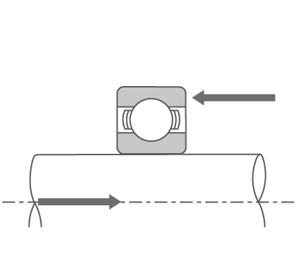
Axial (thrust) load
Load in the direction of the shaft
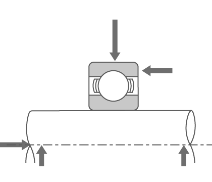
Combined load
Radial and axial load
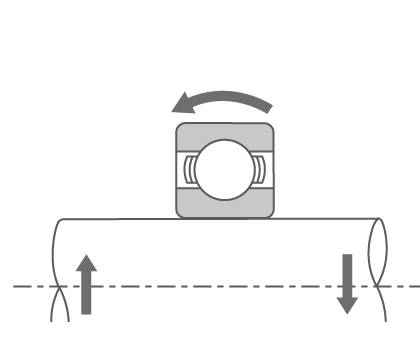
Moment load
Load Distribution Inside Bearings
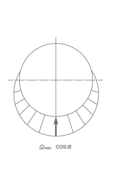
The figures below show how load is distributed inside single-row bearings (angular contact ball bearings, tapered roller bearings, etc.) with contact angle α when radial load Fr and axial (thrust) load Fa are applied.
α: Contact angle
Fr: Radial load
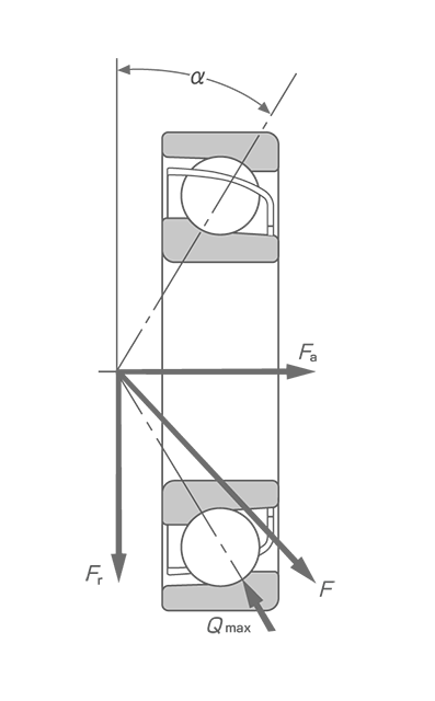
Qmax: Maximum rolling element load
Fa: Axial (thrust) load
F: Combined load (Fr and Fa)