7—Fits and Internal Clearance
Bearing fit and internal clearance have a huge impact on performance. Selecting an improper fit can cause bearing damage such as creep, while an improper clearance can cause bearings to seize.
Fits
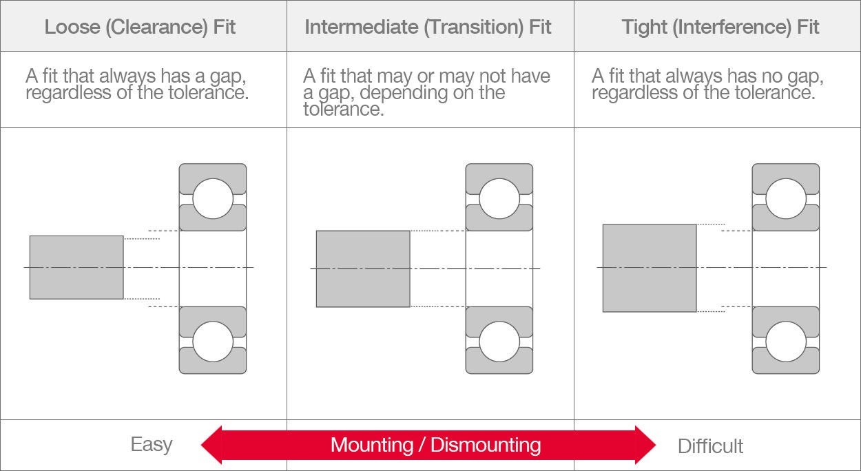
Fits define the relationship between a shaft and a hole. In bearings, this is determined by the setting of mutual dimensions and tolerances between the inner ring bore diameter and shaft diameter or between the outer ring outside diameter and housing bore diameter. Fits use tolerances to account for variations in machining and are classified into three types:
Importance of Fits
Imagine an industrial motor bearing with inner ring load (a tight fit inner ring and loose fit outer ring).If the fit between the shaft and inner ring is reduced due to surface roughness, rising temperatures from operation, or high load, a clearance could develop at the fitting surface, causing fretting*, creep, or other damage. Continued use of the bearing in this state will cause additional wear at the fit surfaces, vibration, and abnormal heat generation.
*Wear from repeated relative micro-slips between two surfaces.
When a bearing is mounted on a shaft with too tight of a fit (excessive interference), stress begins to concentrate and exceed the tensile strength of the inner ring material, making it likely to crack. Even if the inner ring does not crack, lower clearance inside the bearing from expansion of the inner ring during mounting may cause abnormal heat generation.
Always carefully consider operating conditions when choosing a fit.
Damage from Improper Mounting

Inner ring fretting

Inner ring creep with scoring

Inner ring cracks

Inner ring seizure
Creep
When a bearing is mounted on a shaft with little interference and rotates with load on the inner ring, detrimental circumferential slippage may occur between the inner ring and the shaft. This harmful slippage is called creep, and it is more likely to occur when the tightness of the fit decreases.
If the ring is stationary in the direction of the load (inner/outer ring static load), no force that can move the ring will be generated at the fitting surface. However, if the ring rotates in the direction of load and there is a clearance at the fitting surface (or one develops), creep will occur circumferentially.
Interference is often impacted by multiple factors—Let’s look at an example of how interference ciould decrease in a bearing with rotating inner ring load:
- The bearing was press-fit onto the shaft, but the shaft had some rough areas. Press-fitting causes plastic deformation at the same level as the surface roughness, so interference is reduced.
- When radial load is applied, the inner ring becomes compressed in the radial direction, causing slight widening and a longer circumferential length that causes a further decrease in interference.
- Bearing temperature rises during operation, further decreasing the interference.

Example of inner ring creep with scoring
How Creep Occurs
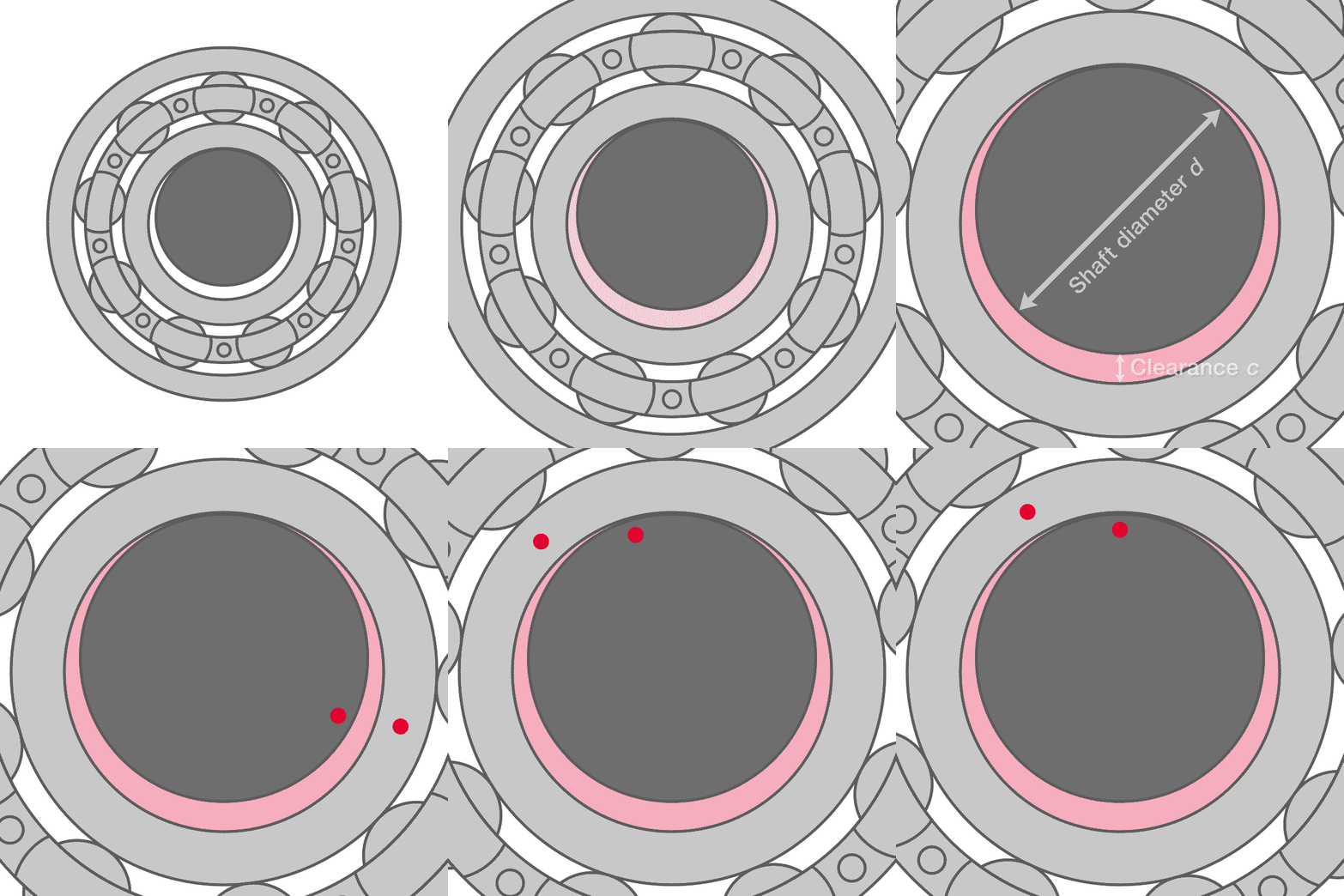
If the interference between the inner ring and shaft is reduced and a clearance (c) develops, the circumferential length of the inner ring side (inner ring bore diameter) π (d + c) will become longer than that of the shaft side (shaft outside diameter) π d in the fitting area.
In this state, when the shaft makes one rotation, the rotation of the ring lags behind that of the shaft, as shown here.
If the clearance between fitting surfaces is c, the bearing will be slowed toward the direction opposite the shaft’s rotation by πc per revolution.
Selecting a Fit
Load Conditions and Fits
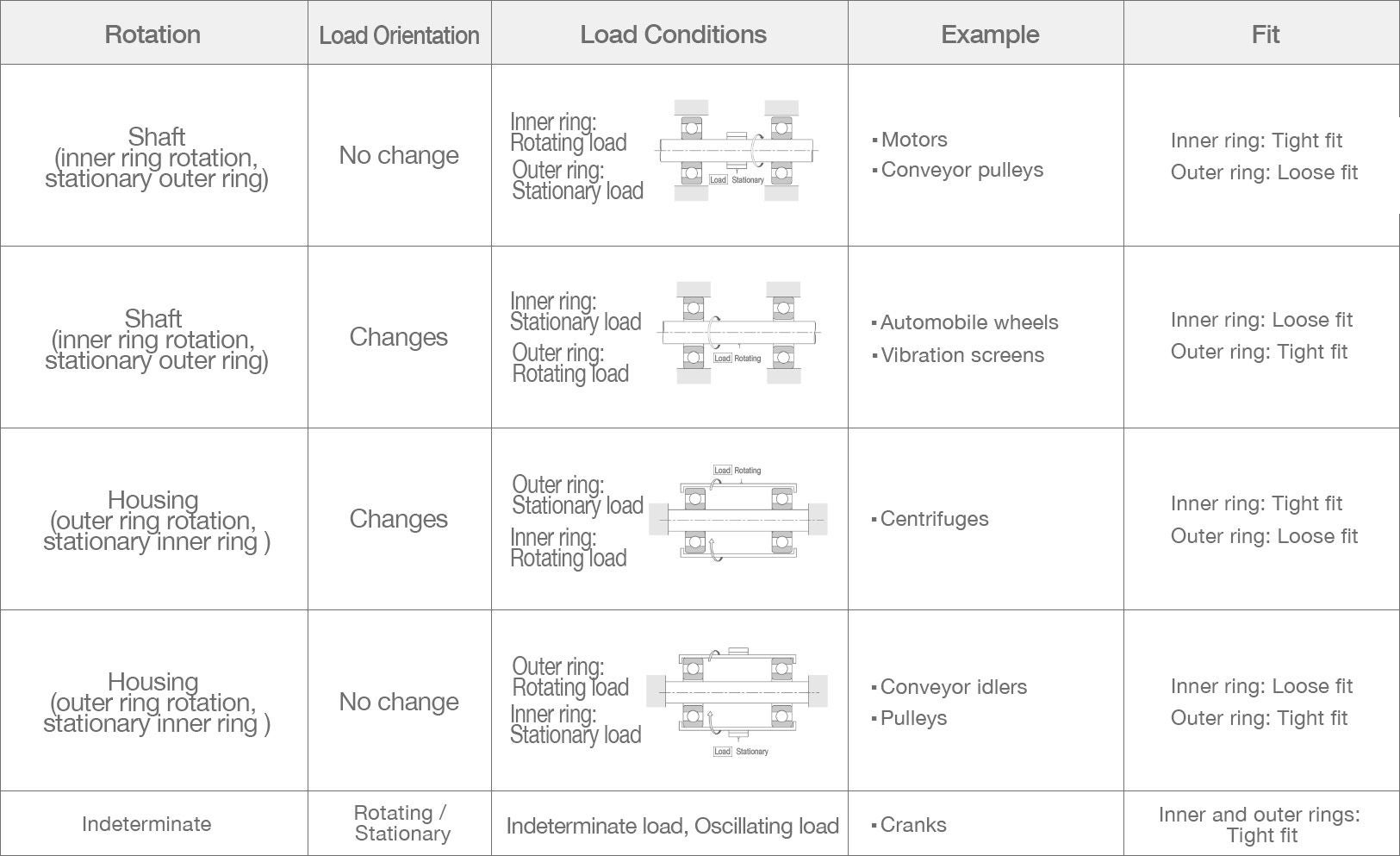
Notes on Load Conditions
- Rotating inner ring load: Load does not follow inner ring rotation (loaded zone on the inner ring changes)
- Rotating outer ring load: Load does not follow outer ring rotation (loaded zone on outer ring changes
- Stationary outer ring load: Load follows outer ring rotation (loaded zone on outer ring does not change)
- Stationary inner ring load: Load follows inner ring rotation (loaded zone on outer ring does not change)
Shaft Fits
Tolerance ranges for shaft fits are arranged in the following order from loose to tight fits:
f, g, h, j, js, k, m, n, p, r
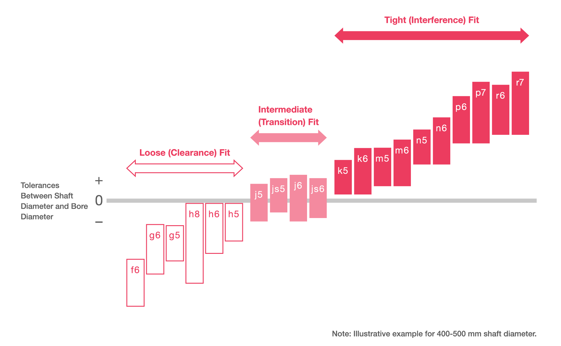
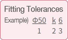
1: Basic dimension
2: Shaft fit tolerance
3: IT* Class: 5 to 10
*International Tolerance: Tolerance classes specified by ISO.
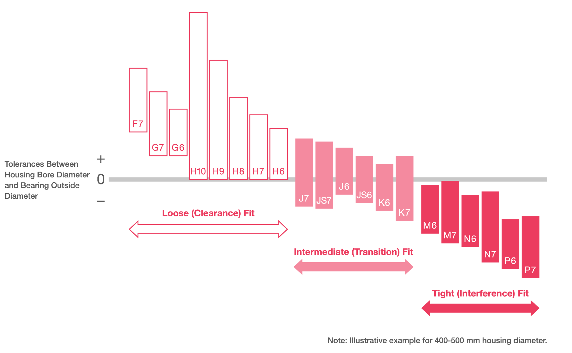
Housing Bore Fits
Tolerance ranges for housing bore fits are arranged in the following order from loose to tight fits:
F, G, H, J, JS, K, M, N, P
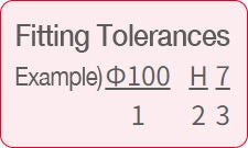
1: Basic dimension
2: Housing fit tolerance range
3: IT* Class: 5 to 10
*International Tolerance: Tolerance classes specified by ISO.
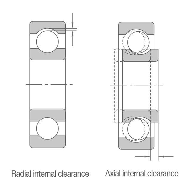
Internal Clearance
Internal clearance (often simply called "clearance") is the amount of play between the inner/outer rings of a bearing and the rolling elements. More specifically, internal clearance measures how much an inner/outer ring can be displaced radially or axially relative to the other ring.
The amount of internal clearance greatly affects bearing performance, including fatigue life, vibration, noise, and heat generation.
Generally, stable measurement values for internal clearance are obtained by applying a specified measuring load to the bearing.
Therefore, the value for measured clearance (also called "geometric clearance" for radial bearings) is slightly larger than the theoretical internal clearance by the amount of elastic deformation (penetration depth) caused by the measuring load.
In ball bearings, we must correct for this increase caused by elastic deformation to obtain the proper theoretical internal clearance. Elastic deformation in roller bearings is minimal and can be ignored.
How Clearance Decreases
Initial Clearance
The clearance (internal) before mounting.
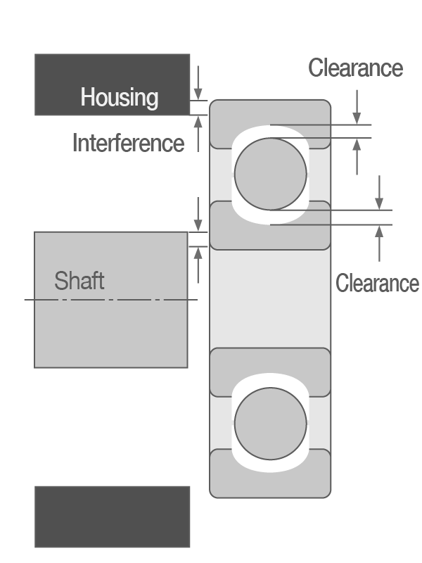
Residual Clearance
The clearance after mounting.
When a ring is mounted to a shaft or housing with a tight fit, clearance will decrease if the rings expand or contract.
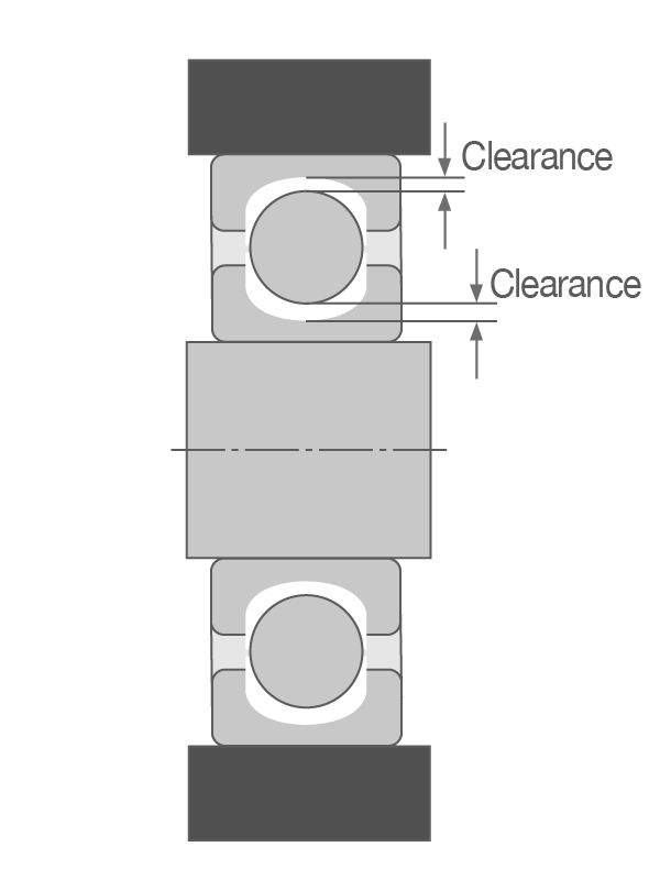
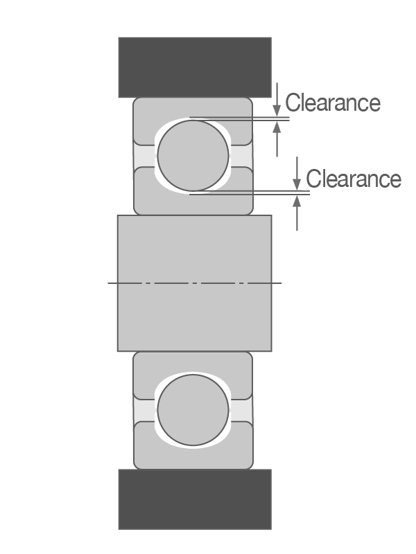
Effective Clearance
The clearance during operation.
Since the housing generally dissipates more heat than the shaft, a temperature difference develops between the inner and outer ring, and the resulting thermal expansion causes clearance to decrease.
Effective Clearance and Bearing Life
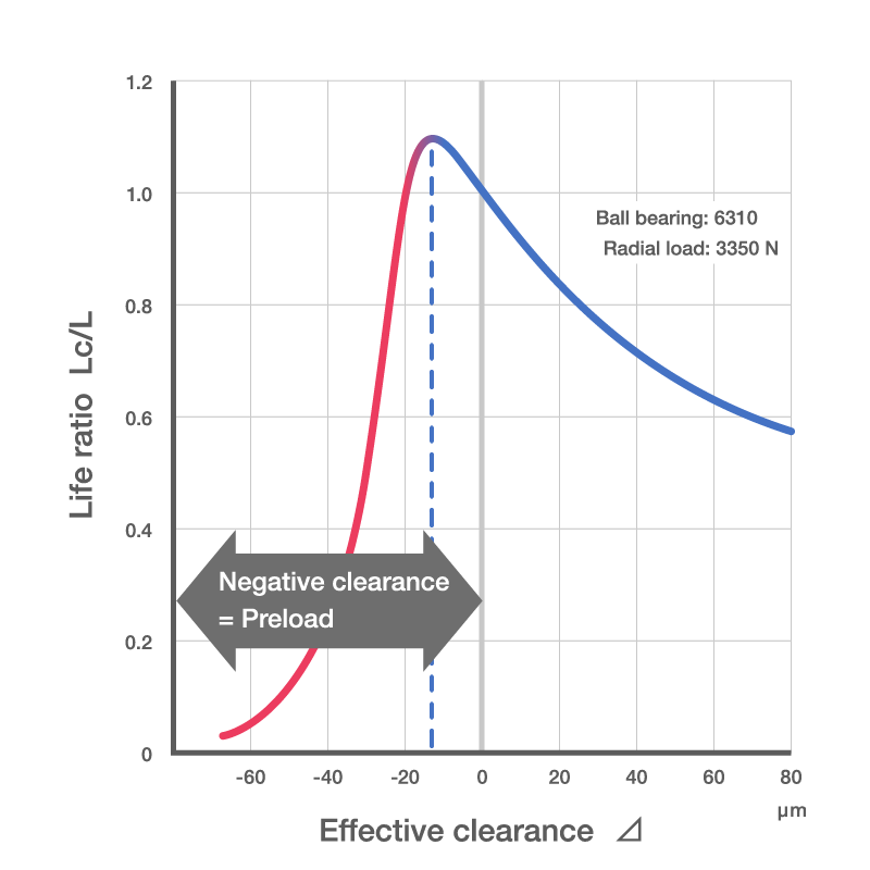
Theoretically, bearing life is longest when the effective clearance Δ of the bearing is very slightly negative. However, if excessive, bearing life decreases sharply as shown.
Therefore, technicians typically aim for the effective clearance to be just slightly larger than zero while accounting for the various errors unique to the actual equipment.
As clearance is so integral to bearing life, ISO and JIS have specified several clearance ranges.
Selecting Internal Clearance
The internal clearance of radial bearings gradually increases in the following order:
C1, C2, Normal (CN), C3, C4, C5
When to use a larger than normal clearance (C3, C4, C5)
- To tolerate mounting errors, such as large shaft deflection
- For high inner ring temperatures, such as when steam passes through a hollow shaft
- When using a higher interference for heavy or impact loads
- To account for the increase in inner ring interference at high speeds
- When both the inner and outer ring have a tight fit
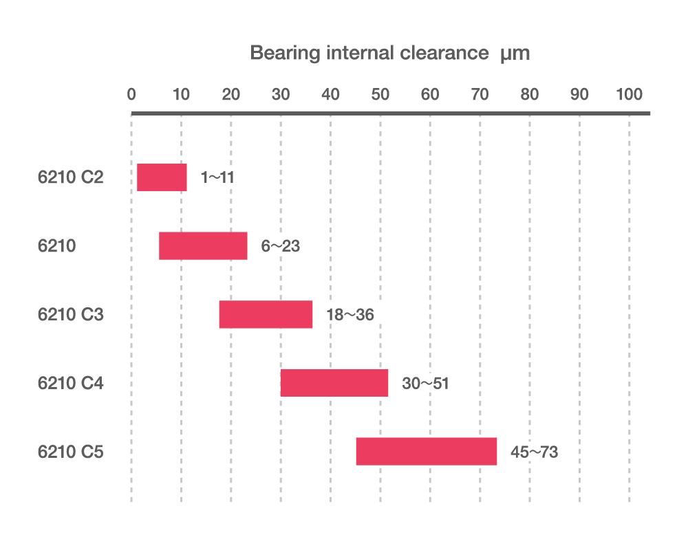
When to use a smaller than normal clearance (C2):
- To drastically reduce sound and vibration during rotation
- When both the inner and outer rings have a loose fit
- When clearance will be adjusted after assembly to reduce shaft runout or similar.
Internal Clearance Codes
Bearing Type | Clearance | |||||
Low | → | (Normal) | → | High | ||
Radial bearings | C1 | C2 | (CN) | C3 | C4 | C5 |
Non-interchangeable* | CC1 | CC2 | CC | CC3 | CC4 | CC5 |
Small/miniature ball bearings | MC1 | MC2 | MC3 | MC4 | MC5 | MC6 |
Deep groove ball bearings | -- | -- | CM | -- | -- | -- |
Cylindrical roller bearings | -- | CT/CM | -- | -- | ||
*Inner and outer rings with non-interchangeable clearances are not compatible with each other due to small range sizes.
In deep groove ball bearings, cylindrical roller bearings, and spherical roller bearings, "E" is sometimes added to the clearance code.
This is an NSK-exclusive code for noise and vibration specifications.

